QUAKE Installation Guide (Video)

Rich demonstrates how to install the QUAKE Stock in your AEG.

Note: The QUAKE has been discontinued.

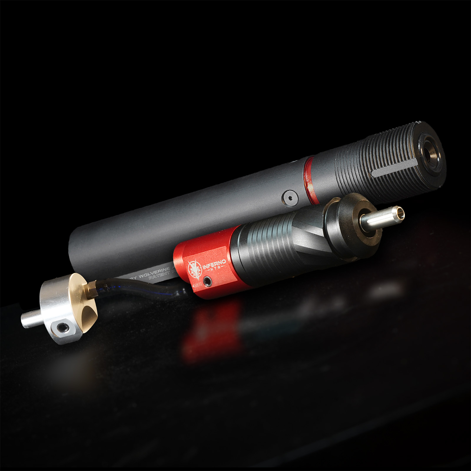
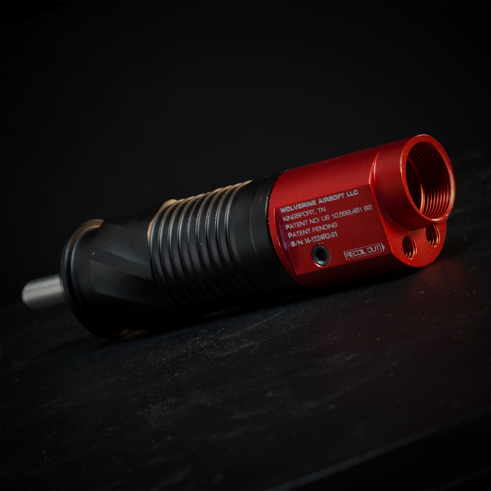
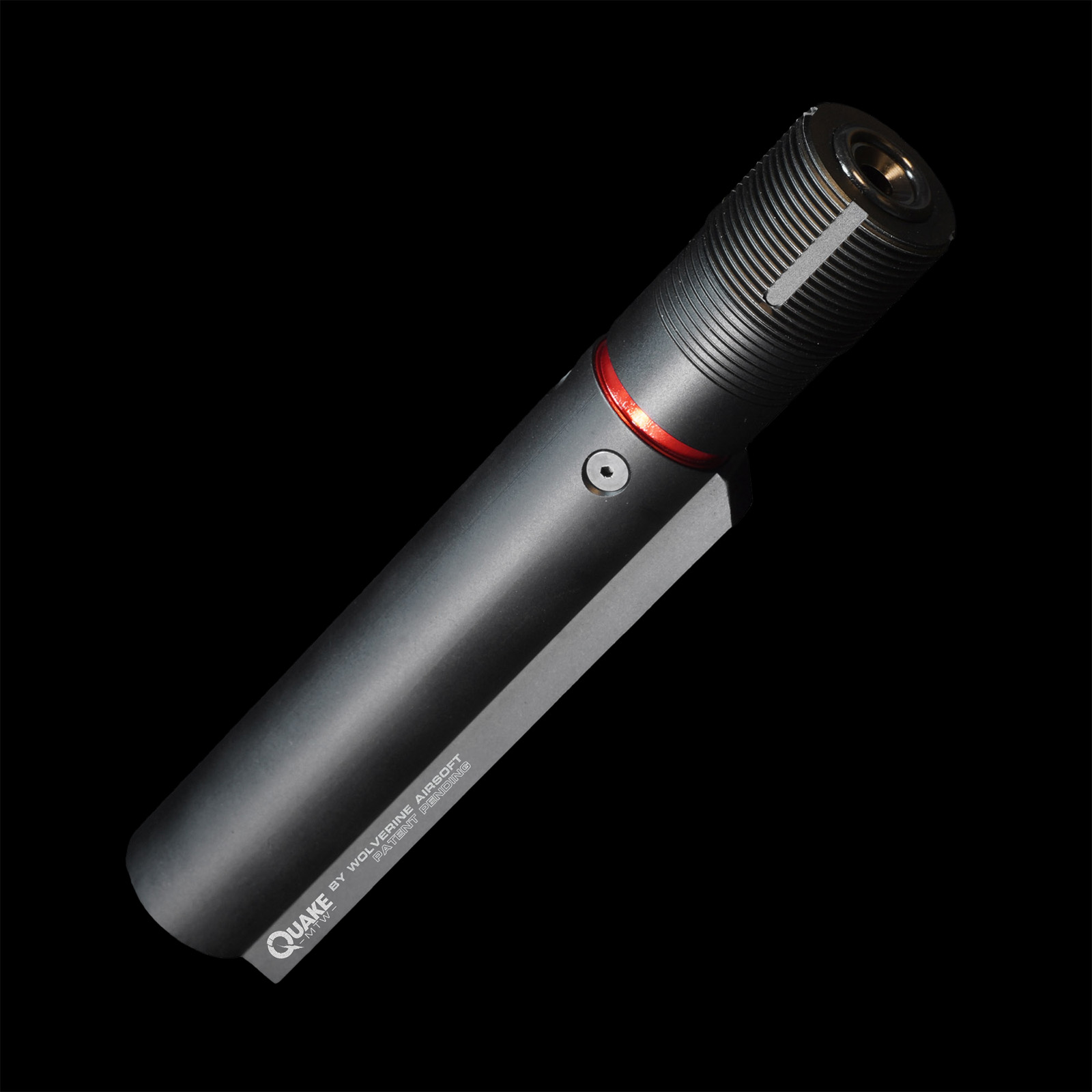
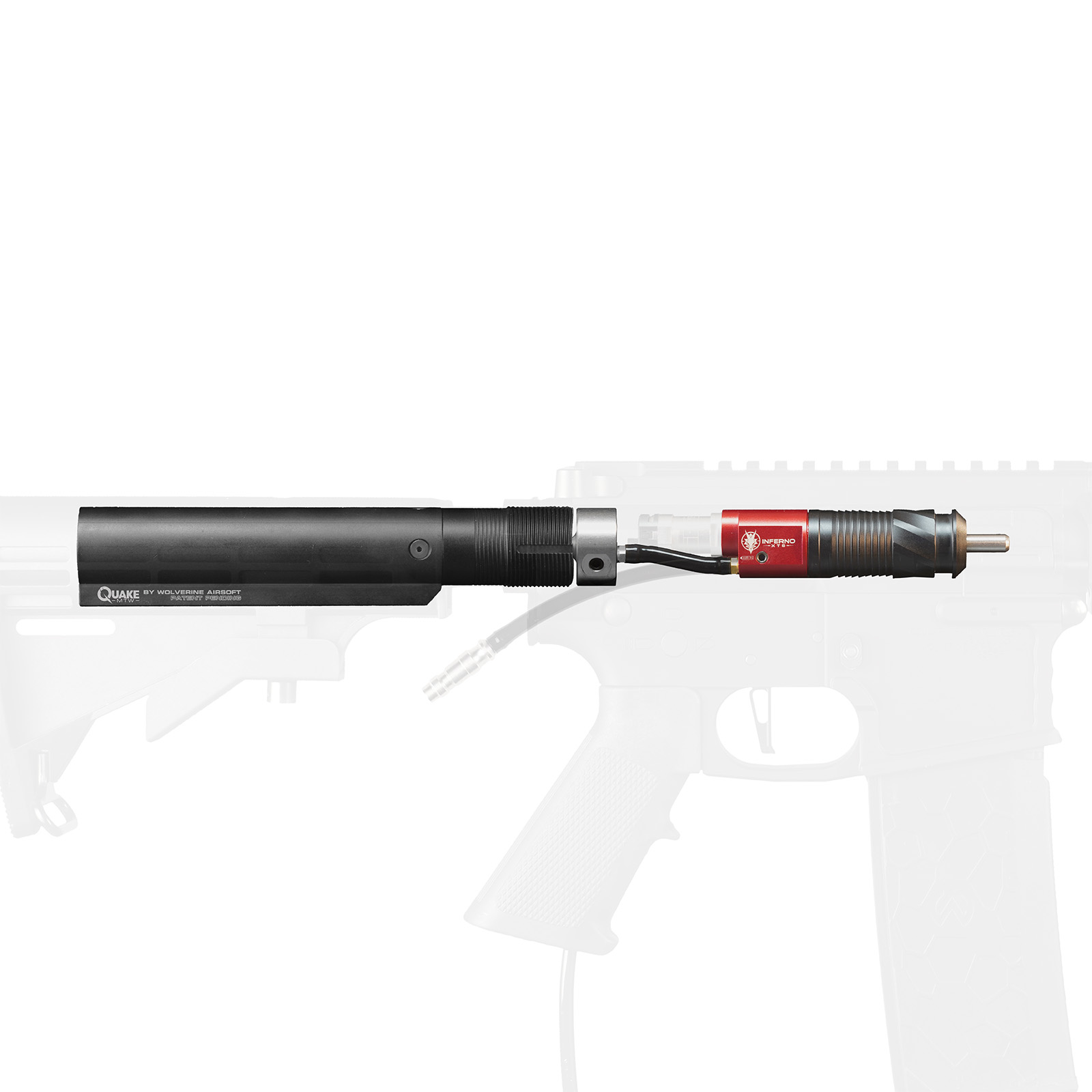
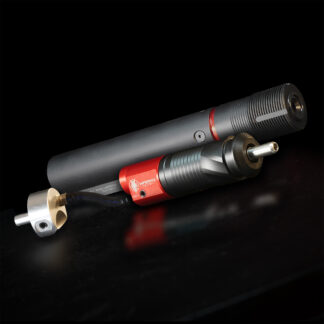
Video transcript: what’s a deck alright so today we are going to take a look at the much-anticipated quake we’re going to go ahead and do the installation here for you first we’re going to take a look at what comes in the quake package main item here is your quake cylinder this will have electric line coming out and also your air line coming out you will also get your quake FCU in the future once these become common we will all actually offer this under without the FCU but for now nobody has these so all packages will include them you will also get this special reduced flow piece of airline you notice it’s this sort of blue tint so it looks different and it’s a reduced flow fitting for your gen 2 if you need to use this with a Gen 1 or an SP we can provide an appropriate fitting for that as well but do make sure you request that when you order it because it will come by default too with fitting that works with our current systems the last piece that will come in your kit is a tee here – supposed to connect tee so that’s the that’s the last piece that’s what’s going to come in your kit the gun we are going to install on today is a vfc 416 we have chosen the VFC because it is our favorite platform to do this installation on because it requires no modification to the lower receiver itself if you have to do a little bit of modification to the gearbox but the receiver itself requires no modification so let’s go over to receive it real quick this is the retaining bushing it has threads on the inside that’s used for holding the stock buffer tube on you’re going to punch that out you can use a punch or if you don’t have a punch an appropriately-sized screwdriver can be used but I do recommend a punch so you don’t kill your screwdriver but just punch it out from the back towards the inside and it will come out at that point your lower receiver is all done now if you’re using other brands of photo receivers there are a couple things you’re going to want to do first off is you want to trim it to what we call the tail piece notice on the VFC we are right at about eight millimeters give or take you want it that length or shorter all right so you’re going to trim it down you can use a hacksaw if you want or we like to use a angle grinder with a cut-off wheel that does it really quickly and neatly whatever method you have available to you you can use for that and when your cutting is so when you’re cutting this down you want to aim for between 0.25 inches which would be right there and by 0.32 which is about the length this is gives you a little bit of room for error somewhere in that range will be fine so if you’re doing a definite different brand that’s what you want to do the VFC is already short no problem there the other thing you’ll need to do if you’re working on a receiver that is not a PFC is you will need to drill this hole album of the bigger it comes at just over five millimeters we need a quarter inch hole so quarter inch drill bit right through the middle it’s pretty straightforward just run it through that’ll make enough room for our fitting so let’s talk about the gearbox here what we want to do on the gearbox is to remove some material to make room for this fitting because the fitting is going to sit right about here and you want to be able to access it to push to connect and disconnect the air lines grab a marker and here is where we want to cut we want to come in right above this screw here and then you don’t have to trim it this far out but it makes it easier if you remove a little bit more material if you want to cut it back here it should work fine but makes it a little bit easier if you bring it up right about here right behind this screw so we just want to cut that whole chunk out of the gearbox now again you could do this with a hacksaw you could do this with an angle grinder that’s what we’re going to use whatever method you have available with and feel comfortable with we do highly recommend you have a tech do this for you so find a good tech they can make this modification pretty easily so we’re going to take it over and we’re going to cut that piece out alright so here we have the modified gearbox on this hand side you can see one thing you do want to make sure you come in above the support for the selector plate here so we come in right above that yeah it took about four or five minutes with the angle grinder and a file to clean up the edges do be sure you know what you’re doing if you don’t feel comfortable with it please find a qualified tech to do it before you work get in touch with us and we’ll help you get taken care of that we have our gen 2 inferno here let’s go ahead and swap the air line I want a quarter inch wrench for the airline now we’re going to take our reduced flow air line I’m going to talk about this real quick what this does is it reduces the power output at a given pressure on the inferno it reduces the flow into the inferno but not into the recoil system so what that does is it lets you run a higher pressure on your recoil system so you get better recoil without running a really high output energy on your gun so you’re running too hot just tighten that down with a quarter inch wrench so now our Gen 2 Inferno is ready to go let’s go ahead and install the stock the receiver now when we go to do that what we’re going to find and different sling plates are done differently this particular sling plate does not have much space right here this cutout is really small so when you go to try to install this what we’re going to run into is that the air line needs more space than that provides you can see that the air line comes right through there we’re going to need to open this up a little bit here again you could use a variety of methods Dremel file if you wanted to file would be pretty tedious now we’re going to just stick it on the mill real quick and take a little bit of a cut out there this is our sling plate that we have opened up a little bit more here to make more room for the air line if we go ahead and install that on this opening here is where the the air line and the wire harness go through it’s not a lot of extra space it’s pretty tight so we need to be careful getting that through there make sure castle net is installed on our buffer tube we can actually go ahead and pull this section off of the wiring on the quake that will actually go get plugged into our trigger board and now we have the output for both solenoids on the trigger board so put this together now we’re going to go ahead and pull the sling plate back off that’s where we’re trying to get so we’re going to go ahead and slide the sling plate get it around the tubing and the wiring where we want to moving and wire and go through the bottom opening and then the screw coming out of the quake goes through the opening in the center of the tailpiece one that we drilled out if we had to drill it out I’m just going to work it in do we get it to sit there now we’re going to take the included lock nut go on the inside of the receiver and here you will want a 7/16 wrench or if you’re lucky and you have one of these handy 7/16 driver so this is the the second reason that we really like vfc for these installations because we have a lot going on here we have tea with the tubing we have wiring going to two different places there’s no reinforcement in the back of the VFC gearboxes so it makes it really easy to do this you can work with a lot of the others but you might have a little more difficult time getting things arranged or you might need to remove a little bit of material to make space go ahead and put it back together alright so the gearbox all back together here goes back together just like normal you need to be IFR fitting for our electronics there we also have our fitting for our airline now we’re just going to put it in the receiver make sure you pull the airline and the and the electronic wires out with the waves back there there we go now there’s really only one step left and that is the trimming of the airline airline comes a little long so that you can trim it to fit your gun and good rule of thumb here is you can always take more off we’re going to go ahead and put this small body pin back in just to get the gearbox sitting in the right position in the gun so we’re measuring to the right place so within in the right place if we look at the fitting here that we’re pushing it into there’s a chamfer section down to a narrower part what we want to aim for is to cut this tubing just long enough that it lines up with the end of that chamfer so the far side of the chamfer from the tubing itself so just where it hits the narrow section that’s what we’re aiming you get a good sharp pair of scissors again and remember you can always take a touch more off if you want can’t add more back on looks pretty good we’re going to pop this back out now we’re going to pull the gearbox forward and push the line down get it in that fitting push it all the way back up against that fitting so it pushes in place and locks in place and then we just have to hook the electronics together and with that we are installed at this point the reassembly just goes exactly like normal your body pins back in reassemble the upper onto the lower put your grip on all that kind of stuff we won’t go over all of that in this video to go this is to show you how to do the installation a couple things I would highly recommend you take a look at there is a good bit of recoil provided with this system lots of vibration keep in mind that a e/g parts were not really designed to stay in place under a lot of vibrations so we highly recommend using some blue loctite on parts you don’t want to fall out things like if your selector squid switch has a screw to hold it on highly recommend removing that putting some blue loctite on it to keep it in place if you have a screw that holds on your mag release i recommend that as well grip screws lock tight those lock tight is your friend here it’s going to help keep everything together when this thing is kicking and you’re out there have a good time so that is the quake installation also recommend looking at our alignment video again with lots of vibration things tend to get shaken out of place highly recommend looking at that video we on all of our quake installations will put set screws on each side of the gearbox to keep it locked in place so that as things shaken they can’t move out of place also lock tight dough’s and oxide is your friend so thanks for watching guys that is the quake installation and leave us comments or questions in the comments section below and thanks for watching you

Quake Maintenance Guide (Video)

Rich demonstrates how to disassemble, maintain and reassemble the QUAKE Stock.

Note: The QUAKE has been discontinued.

Video transcript: one sec all right so this is going to be the technical overview video for the quake we’re going to this is focusing on the mechanical portions we covered the electronics and helps tuning in some other videos so this is just going to be dealing with how to disassemble it do any maintenance you might need to do on it and such so we’re going to go ahead and start with a 7/16 wrench or driver as we have in this case or skimming loosen this up now let’s just pull out the whole sliding mass spring system and for most of for basic maintenance that’s really all you’re going to need to do is take that off lubricate your o-rings these two are rings because there’s only two dynamic o-rings in the system and you can put it back together we’re going to go ahead and break it all the way down here and show you what’s inside in case you need to break it down further now before we get started on the more complete teardown I want to say two things one we don’t really recommend your average person do this there are some small components inside that can be damaged if you don’t do it properly if you’re having a problem with the with the core of the system it’s better to have us dealing with it on warranty or take it to a qualified tech to have them help you with it if you are going to do it there are a couple of tools that you will need you will need a 5/64 allen key and then you will need the one that is probably gonna be a little more difficult to find which is a 35 thousandths LMT this is a very very small allen key they can be found but you might not be able to pick one up at your local hardware store so before you try to do this make sure you have found a source or these tools to take this apart what we’re going to do is take the screw out using our 560 for this point this whole piece can come apart now this is the core of your system this is where your valve and your airline go in this point we can just unthread these two pieces there are no o-rings on this piece here and then this is where you will need your very very small allen key there’s a small set screw which sits right here which we’re just going to back out and then you can get access to your valve if you need it notice I didn’t pull this plug through I recommend just leaving it there unless you really pull that out if you need to completely pull this part you can pop the connector off of here and you can unscrew the valve do take care when you are reinstalling this valve take it out again you’re dealing with very small parts here the o-rings on this valve can easily be damaged if you’re not careful just be very gentle in screwing it back in and just make sure that you don’t feel any binding at all if you feel any binding back it up a little bit and work it until everything goes in nice and smoothly lubricate those o-rings a little bit before you put them back together again just to make sure you don’t damage an o-ring most people will never need to do this again this is just showing you the full breakdown in case you need it there are three o rings on the body here these are all the same o ring and if you need to replace them you’ll notice that there are actually six grooves three of them are air grooves and three of them are over in grooves the grooves that don’t have a port in them are the ones that get the o-rings they have one two three airings and then you have three grooves that have an airport and those do not get a rings that’s that will go ahead and put this back together here stick the air line through plug the valve in there is a small detent on the valve body here that’s what your set screw goes into you’ll notice it’s lined up with the air line so if we line that up and you don’t need to tighten this all the way down it just needs to get flush that’s just keeping the valve housing from where when we tighten the threads down go ahead and install the piece back in make sure you tighten that down and then this can go back into your buffer tube the threaded hole here goes on the bottom side of the buffer tube that’s where that little screw we took out at the beginning goes into just make sure you guide your your wiring and your air line through that’s always when dealing with wiring don’t force anything if it doesn’t want to go back up check what’s sticking and try again there we go so you can see we can find the threaded hole we can rotate this piece until we get it to line up and get our 5/64 you will want to put some Loctite some blue loctite on this or we use vibra tight which resists vibration but isn’t locking like like Loctite is so screw that in this you will want some blue loctite on the large side of the mask goes to the back real quick if you do need to replace the o-rings there’s one on the outside one on the inside just two overhangs can’t really mix them up so the large side of the mask goes to the back towards the spring at the back here we’ll talk about this real fast there you have a spring then you have a little rubber washer and then you have this small retaining plate that the spring sits on the spring goes on then your mass and that whole assembly goes into the back of the system simply tightens down again using our 7/16 wrench or in this case a driver there’s not a need to over tighten that because when you put the whole system together the way this is designed with the nut on this end once it’s installed in the system and then the tightening of the castle nut the tightening of the castle that actually stretches the whole thing and puts tension on on this bulb as well as the nut at the front so that keeps everything locked in place so you don’t need to go crazy on this bolt just tighten it in place and you are all set so that’s how you carry down your quick stock if you have any questions leave them in the comments section below as always comments or suggestions are welcome and give us a like on Facebook follow on Instagram and a subscription here on YouTube so you can get all the latest updates on Wolverine airsoft products thanks for watching guys