Troubleshooting Alignment Issues (Video)

Rich explains the best way to check and correct alignment issues on an M4.

Video transcript: hey guys this is rich and today on what the tech we’re gonna take a look at alignment what it is how do you go about checking it alignment one of those bug buzzwords anybody that’s been around HPA for any length of time is heard but a lot of people don’t really understand it or don’t really feel comfortable with checking it and adjusting it so we’re going to take a look at how we check alignment and some ideas on how you go about fixing it so let’s jump right in alright so the way people have been checking alignment for quite a while and this is the way we suggested quite a while ago is basically this is your barrel this is your hop-up basically shining a light up the feed tube and then visually looking down the barrel and you can see generally when you’re looking down there where you’re gonna be able to see is you’re gonna be able to see the barrel you’re gonna be able to see the nozzle as well and then now the nozzle will either look nice and centered like it should or well look off to one side or high above something like that and you can see where you need to adjust it so let’s talk about why that method is not wrong per se but I’m not always completely accurate what ends up happening sometimes is the hop-up fits into the front of the gearbox you can actually get into situations where if if that fit between the hop-up and the gearbox is tight for instance again here’s our barrel it will be held in place by the gearbox here’s our gearbox over here and it’ll it’ll need to line up with the gearbox over here but that line is not straight with the barrel so but it gets forced into that position then what you end up with is one of two things either you bend the barrel a little bit to make it fit in position or the parts within the hop-up themselves shift a little bit with respect to each other so that it can line up but either way the end result is when you’re looking down because it’s still held Center the hop-up itself is held centered on the gearbox real closely it’ll still look like it’s centered it’ll still look good in your eye isn’t gonna pick up on the slight curve in the barrel or the parts being being shifted a little bit sometimes it’ll it’ll look good and then you’ll take it apart and you’ll find that the nozzle maybe has some marks like it’s rubbing on the hop-up or or something along those lines or it’s still not shooting real well but it looks good so we’re gonna talk about an alternative method for how to how to check the alignment that works a lot better so what you’re gonna need is your gun and a donor barrel and that’s about it you need those two things and maybe you’re gonna want to do it in a pretty well lit area so you can see clearly but other than that don’t need a flashlight don’t need anything like that so let’s talk about how to do this okay so what we’re gonna do is going to take our barrel as you can see we’ve got the system installed in the gearbox and we have removed the hop-up and barrel from the gun you want a barrel with the hop-up off and I’m gonna do is I’m going to slide the barrel down the inner barrel if you watch be able to see it come out right there and all I’m gonna do is this lets me visually check whether it’s lined up you can see if the nozzle actually lines up correctly from the side and you can look from the bottom and see it lines up well from the bottom now there may be some guns that this is doesn’t work real well on but for the most part especially any stage damn for this is by far the best way to go about checking and you can see where you need to adjust it if you need to adjust it alright so you found that you’ve checked your alignment and you found that it’s off for some reason we can’t cover every single gun and how you would go about fixing it we can’t even really cover every single variant because there’s a lot of them but give you some general ideas specifically for m4 style platforms as far as how you might go about adjusting it put the receiver apart here there’s basically two ways that the that the alignment can be off it can be off vertically it can be off so side to side of the two generally side to side is a little easier and more reliable to fix generally basically what you’re gonna do is you need to space the gearbox on the two sides here between the receiver and the gearbox generally we put just a drill and put in some set screws on each side and that allows you to adjust it so right down in this location I put a screw in on that side I’m gonna screw down in on that side and then you can adjust it back and forth and you can get it centered right where you want and once you get it you can lock tight those screws in place and they’ll never move and it reliably goes back together the same way every time vertically is a little more a little more tricky if that’s off sometimes because in theory this shouldn’t this gearbox shouldn’t be able to move vertically in theory it’s held in place by these two pins however sometimes those pins either are not in the right location or they are loose so the gearbox has some slop in it one way or the other if it’s off vertically generally what we will do is we’ll remove this front pin for just remove that guy and and just try to adjust the vertical with the back pin in place the the back body pin there in place on a lot of guns the reason that most most often when we see the alignment off vertically what we see is it’s too high the nozzle is sitting up too high in the receiver usually this is because the buffer tube is going into the back of the gearbox this one’s been modified you can see so that’s not an issue on on this this platform at this point but it’s going into the back of the gearbox with the buffer tube adapter and that’s getting tightened down and that’s pivoting the gearbox around at this point and it’s pulling it rotating the gearbox backwards or counterclockwise which pulls the nozzle up if that’s what you’re finding what you’re going to want to do is loosen the buffer tube up and tighten down the grip screws first because those grips screws are pulling on an angle like this and if we remove this pin now when they’re pulling they’re pulling the front of the gearbox down lower so you’re gonna if it’s too high which is by far the most common thing we see with alignment on M4s just go ahead and tighten the grip down first maybe tighten it down a little bit at a time and you can go back and check the alignment as you go put the top back upper receiver back on and check it a couple times and then then Snug down your your buffer tube screw and don’t just go nuts on that Snug it down as much as it needs to be but don’t don’t crank it down super tight because you might might pull it back up usually that those methods will will get you lined up sometimes in more extreme cases you may find that it just the gearbox can’t sit in the right position in the lower receiver this usually is because people are using a mismatched gearbox and receiver they’re using a different brand gearbox than the receiver they’re using we don’t really have time to go into how to fix that issue right now but generally we just recommend use the same brand preferably the same gearbox that came with the gun but at least the same brand gearbox so that you don’t run into that type of a situation that’s generally how we go about fixing basic alignment alignment issues I highly recommend using this method running the barrel down visually check how it lines up with the nozzle because it’s going to make it makes it much easier to pick up on misalignment then the way it’s been done in the past thanks for watching guys I hope this was helpful to you if you have any questions or comments be sure to leave them in the comment section below and we look forward to seeing you guys out on the field

Installation: JG Bar 10 (Video)

Rich demonstrates how to install the BOLT in the JG Bar 10.

Hole measurement guide as mentioned in video.

Video transcript: hey guys this is rich with Wolverine airsoft and today we’re going to take a look at how to do the installation on the brand new bolt from Wolverine airsoft so let’s jump right into it on today’s what the tech ok so we got our bolt here and this is a demo of kind of what the production packaging will look like this is the bolt with cylinder as you can see bolt plus cylinder threads in the long packaging the boat without cylinder will come in a shorter packaging I’m just going to go ahead and unbox this and kind of show you a couple things first thing to point out is there’s this little insert and we packaged a little differently on the other packaging on this insert this is important important is a QR code here and there will also be a URL to register your product for warranty to be eligible for until you need to go and to sign up your product at this address ok don’t miss that this is something new we’re starting with the bolt and we’ll be doing this moving forward with other products as well so as soon as you open it right there up on the website you can scan the QR code with your smartphone and go right there to register it it just takes a minute inside the packaging we have a bunch of packages have a couple screws to hold on our trigger switch of our battery have our bolt with cylinder and we have our wire harness and our airline fitting that’s what’s in the packaging if you ordered the bolt without cylinder it’s going to look like this just won’t include the the cylinder we offer so for the demonstration of the installation today we’re going to be installing on a jg bar 10 the G spec model but they’re all pretty much the same so we’re going to do that installation first and we’re going to do that without the cylinder and then after we do the installation after we go through the installation we’re going to talk about some of the different brands instead of some of the idiosyncrasies between the different brands the the differences things you you might need to account for depending on what brand you’re installing in so let’s go ahead and get the gun up here so we got our gun up here disassembly is just like you normally would with these we’re going to go through this quickly not show all the details there’s plenty of detailed instructions on how to do this it’s just a very common gun all right so we got this disassembled there are two basic things that we need to do we need to install the trigger and we need to install the system inside the cylinder we’re gonna do the trigger first what I’m gonna do is just disassemble the trigger box and we are going to remove all the Sears out of this system which is happy days because they’re what always likes to break we’re out so you’re going to completely remove all of the Sears from this system so there’s four small screws and then you’ll need to unscrew the screw that holds on the safety lever all of your Sears spring assembly all we’re going to have left is our trigger this trigger spring here and then our two adjustment screws they’re all the Sears can get disposed stuff s can the bolt stop next step is going to be to attach the trigger switch through the trigger box I’m just going to go ahead and pull all the screws out and such so they don’t get lost while we work on the trigger box you know if i reassemble this take a look at where the trigger is going to sit this is our wiring this is your trigger switch and that little orange button gets hit the battery is connected to the solenoid and the solenoid it’s going to sit right there you can see the tab on the side of the trigger the safety tab now will engage the trigger switch so what I’m gonna do is I’m going to get the 1/16 drill bit that is included with the kit I’m just gonna mark a spot kind of find where the trigger wants to go I’m gonna hold it in place once it’s about where I want and I’m just gonna kind of spin the drillbit in the top hole pressing down til I get a little mark this position is not super critical because keep in mind once we put that screw in we can rotate the position of the switch to get the right amount of engagement but just need it in basically the right location get as close as you can to where you want it and then you can adjust it with the rotation afterwards now we have our two little screws and I’m going to take this drill bit now and I’m going to drill the hole all right before I drill the hole if you have a center punch this is nice use for a center punch it’s not absolutely necessary but it helps keep the hole where you want it helps the drill bit not walk so just punch that we’re going to go ahead and pull this off just keep shavings out of the trigger mechanism and drill the hole we’re going to try to keep the shavings as much as we can out of the other parts so as you drill preferably this would be done in a separate location from your parts I should have mentioned that earlier I’m doing it on camera so you can see the process there’s a hole and we can clean up those shavings here it’s a good time to mention that the system does have a built in filter element inside the air fitting but as with any pneumatic system keep it clean keep dirt debris metal shavings all that kind of stuff out of your systems and it’ll be a lot happier so let’s go ahead and grab our trigger box or screw this is a t6 driver start bit screw a self-tapping so there’s no need to tap the hole or anything just thread the screw in not going to put it in real tight just yet because I’m going to go ahead and reassemble it with the other half when I reassemble it I’m going to take this short lead and I’m going to put it up through the opening where the spring guide stop was previously you can go ahead and put it together like that make sure nothing’s pinched now I’m just going to check you can see my triggers and quite engaging the switch so I’m just going to rotate the switch a little bit till I’m getting done getting engagement then I’m going to go ahead and tighten it down a little more we should be good we do include a second screw if you want to put the second screw in you can we never bother with it because we’ve found that it’s just there’s nothing putting any pressure on the switch body itself to move so as long as you snug the one screw down there’s just really not a need for the second screw but we do include it in case you would like to do that now all I’m going to do is go ahead and put the remainder of the screws back into the trigger box and the safety lever on and at this point I can check once the safety lever is back on I can check that the safety is actually stopping the trigger before it hits the trigger switch so if I have it on you can see I’m not engaging the switch safety off I’m able to hit the switch just going to go ahead and reinstall the rest of the screws so with all the screws reinstalled we are pretty much done the hardest part of the installation which was just the wiring as you can tell it was not that difficult one thing I did want to mention was depending on how you have the switch positioned exactly this screw here you may want to loosen this up rotate the switch out of the way and install the screw and then reset the position on that so let’s go ahead and set that aside muscat jump into the cylinder the cylinder we’re just going to disassemble as per usual again there are instructions online if you need help with that we use into small allen wrench all the internals of the cylinder can be set aside we won’t be using them now we’ll take the bolt and we’re going to slide it inside the cylinder the airline hole needs to line up with the slot and we like to bend over the shortly wire lead there so that it slides in easily just like so we can go ahead and install the cylinder head again use the allen wrench to Snug it down don’t over tighten than that the threads on most of these cylinders are not terribly strong don’t over tighten it just so I get down enough that it’s not going to not going to move around so there it is installed inside the cylinder so we have our cylinder done we have our wiring done really all that’s left is routing the air line so rounding the airline we got our receiver back out here really we just basically need to drill one main hole and that is a hole in the receiver here the way this works is the airline fitting will go through the receiver and thread into the bolt itself like so with that being held in place by the receiver when you cycle the bolt all that you’re doing is sliding the cylinder around the stationary unit itself so what we need to do is we need to drill a hole in the receiver to allow the air line fitting to go through now on standard jg and tokyo marui vsr-10 systems there’s a really easy marker and that’s this moulding mark here we’re just going to drill our hole right in the middle of that well post a link in the description here for if you’re doing other rifles where this molding mark is not there how to measure where exactly you should put the airline fitting so let’s go ahead and and drill that hole we’re going to need a quarter inch drill bit again I’m going to go ahead and center punch just to keep us on target then you can go ahead and drill again we’re doing this all on video but if you’re doing this please do it in a location away from your system so that none of the shavings get get into the bolt itself so we got our hole drilled again I was using quarter inch drill bit keep in mind this is a quarter that the shaft on this fitting is a quarter inch so if you use a quarter inch drill bit you may find that it’s a little tight still we could force it through but all I’m going to do is I’m going to over drill it a little bit just kind of work the drill around a little bit to open the hole and there we see it fits in there nicely now all right with the hole for our airline drilled we’re really ready to just go ahead and put everything together we’re going to take the cylinder again check that the whole 3d air line fitting is lined up with the slot make sure that the wiring the little wire lead is inside the cylinder we don’t want it getting caught when we install it I line up my threaded hole for the airline fitting with the hole I just drilled put my airline fitting through thread it into place wiggling the cylinder around a little bit helps sometimes to make sure that you aren’t catching the edge of the cylinder on the lip of the airline fitting all righty now we just have to do pull the electronics through I’m going to use a small screwdriver or an o-ring pic or something like that pop the leads through now I’m going to take my trigger box I’m going to plug it in and this fitting is going to sit right where your Sears used to go you can see it right up in that area and then the trigger box will just attach as per usual and with that we really are pretty much installed want to mention a couple more things when you install the airline this will use a quarter inch wrench the airline will thread into that fitting we do put some thread Locker on the threads of this fitting before we ship it however if you assemble and disassemble this multiple times that will wear off a little bit of blue loctite something light while we do recommend on the threads of this piece because it is the stop when you’re cycling the bolt so too much wiggling and without a being held in place can cause it to work loose just install the airline take a quarter inch wrench or an adjustable wrench just tighten that down okay so got this all set up went ahead and put our trigger guard back on and we can I plugged in a battery to our wire harness just going to check that functions when you pull the trigger everything is doing what we could it could also air test it at this point only thing left to do is to figure out where we want the air line to exit the stock talked about a couple options they’re probably difficult to see on the camera but there’s an opening at the back of the stock from your trigger area back to the stock that’s where both our air line and our wire harness are going to run back through there into the stock we include a long length of air line with the unit so if you want you can run the air line back and sit at the back of the stock say behind the sling mount if you’d prefer you can make it exit at the base of the grip still a hole there or if you would like the easiest as far as routing is to just drill a hole right about here and have the air line just exit straight down and come out the front it’s really up to you you know different people are going to have different preferences as far as how they route the air line but those are some of the more common options as far as that goes alternatively if you are running this is the this is the barre tan same with the VSR if you’re running the co2 adapter and storm regulator inside the stock you don’t drill a hole at all you just run your air line back to the back we’re going to pop the cap off the stock here and that whole assembly just fits up inside there those are some different options on this one we plan to run the co2 in stock so we’re not going to drill a hole on this one but I’m going to go ahead and run the air line and the wiring through so you can see how it all goes back together first I’m going to feed the air line through the opening goes to the stock see it got coming out the back that one’s good disconnect the battery flip this around and this is gonna go right through the same opening get fed back both of those can go through no problem the only thing that is a little bit tricky about putting this back together see if I can show you on camera here is where these two go through there’s a tab on the back end of the trigger guard that fits into that opening both of those lines both the wiring and the air line they need to sit above that tab so I’m just going to work them up and over don’t you get that situated slide the tab into place as per usual generally just lightly lightly pull on the air line and the wire harness do not just yank on it just to make sure it’s not not bound up anywhere then the whole thing goes back together put our screws back in one thing I will mention on the bar 10 this front screw if you tighten it down too much it’ll make the mag release catch stick so if I hang it down more and see if I push it down it sticks so just loosen it up just enough that it pops back out the other thing you’ll note you may notice is that on some of these tightening or loosening the two screws will affect how freely the action slides you can see mount slides very nicely no resistance that’s just because there’s some play in between the receiver and the barrel and the hop-up unit how tight you tighten down the different screws affects how exactly they line up so if you’re noticing there’s a lot of drag on the bolt when you’re trying to cycle it check that other than that we are completely done you can see at the back I can plug in my battery no problem then check that everything’s working which it is and again at this point you could just run your airline out say through a hole here or in the grip up here if you like and you can trim your airline to whatever length you need and just use the push to connect fitting to attach to it battery gets stowed in there we will be installing the Wraith and co2 adapter and regulator and they will fit inside stock as well alright guys so that’s it for the basic installation again this is a jg bar 10 for the Wolverine airsoft bolt so let’s jump right into it on today’s what the tech

VSR Clone Compatibility (Video)

Rich discusses compatibility of the BOLT with JG, TM, and WELL brand VSR clones. While they are all said to be VSR compatible, there are slight differences that are important to understand for installation purposes.

Video transcript: so as with everything in airsoft there are a million variations lots of different brands that all claim to be compatible or clones or something or other but they don’t always work out quite as smoothly as you would like bolt actions are no exception right now I’m just going to talk about specifically some of the vs are clones and not get into other platforms and such we’ll be providing more information on other platforms as it becomes available but right now I just want to show you three different brands have Tokyo Marui I have JG and I have well and these cylinders to the naked eye all look pretty much identical a little difference in the finish on the well versus the other tube but nothing major problem is none of these are the same if we are talking tokyo marui tokyo marui cylinder as you can see by being all scratched up and destroyed there the cylinder head is actually pinned to the cylinder in order to get the cylinder head off you have to drill that out it’s really not fun to do we strongly suggest that if you are getting the tokyo marui doing a tokyo marui you get our cylinder it is much much easier well worth the money in our opinion versus messing with trying to drill out the stock cylinder however we do offer abs are compatible cylinder head now what’s the difference between the VSR and the j the tokyo marui VSR and the jg bar cylinder head well other difference other than being pinned between jg and TM is the threads on the end they’re close but not the same you notice the vs our cylinder head does not interlock with the JG cylinder where’s the jg does okay sir slight difference in threads we do offer ATM compatible cylinder head but we really don’t recommend it it’s much much easier if you just get our cylinder the other difference between the jg and the TM is the depth of this cut here now this is something we discovered it’s really really subtle and we kind of discovered it a little later in the game we’re going to be updating the design of our cylinder in the future so that it works with both handles both the jg and the TM type handle but basically the TM spec this section here is just a tiny bit wider so if you try to put a JG handle on either a TM cylinder or on our cylinder at least the ones will be will be have starting out you’re gonna find that it doesn’t want the back cap here doesn’t want to slide on if you want to put the cylinder in your JG it’s really simple to just remove a little bit of material from that flat there you have to remove about ten thousandths worth of material off of that flat to get it to fit in there but we really recommend with the JG just getting the without cylinder anyway because there’s not really a need for it like we said it comes apart easily you can just use the stock cylinder but something to keep in mind if you’re going to be using our cylinder with the JG body and handle and back cap at least at the beginning until we get second batch of parts in you’re gonna need to remove just a tiny bit of material from that surface to get it to fit smoothly that’s JG and TM then we have well-well just doesn’t quite do things like anybody so well uses the JG speck threads so it worked with the bartend cylinder head however the internal diameter of the cylinder is just a little bit tight compared to the other specs you can see the unit will fit in there it will slide but it is tight now you can use it like that we haven’t tested a lot of the wells but as far as we know it would work like that however it’s going to be tight there going to be more resistance on the bolt Pole now you might say why don’t I just use the bolt with cylinder well now we run into the second problem the shaft on the well cylinder is just a tiny bit smaller than the shaft on the tokyo marui spec cylinders the diameter here so you could if you wanted to get an aftermarket handle and it was compatible with TM and at that point you probably could make it work that we haven’t tried it or you will need to either wore out your existing handle or something along those lines so well is not we are not saying is exactly compatible it could be made to work and I’m gonna give you an idea how we would go about doing that so if you have a well and there may be other brands like this don’t know this is from a well em bo3 or something along those lines we’re gonna see if we can make this work as far as we can tell it’s mainly the back bushing there the way the system is designed there’s a Delrin bushing on each end here the front cap is Delrin and there’s a sleeve at the back that is Delrin they are a slightly larger diameter than the danver diameter of the bolt itself they are what is rubbing on there and what’s kind of causing problems this is a undertake at your own risk the type of modification because we know people out there want to put them in everything we’re gonna show you how you might do it so first thing I’m going to do is just get some tape I’m going to tape around the body right below where the Delrin ends and what I’m gonna try to do is I’m going to take a little piece of 400 grit sandpaper and I’m gonna try to just remove a little bit of material from this Delrin bushing tape is just protecting the aluminum from getting the aluminum housing from getting scratched work it down a little bit the Delrin sands pretty easily alright so we got this sanded down took about 10 minutes of sanding removed the tape you can see it runs fairly freely now there’s your soul a little bit of drag but not too much for our purposes that’ll be okay in the future when we do this we will just put this in the lathe and turn it down a little bit on the bushing there but we’re trying to trying to give you guys a solution that anybody can do with basic tools if you want to so again that’s for the that’s for the well there may be other brands out there like that alright guys so that pretty much wraps it up as far as the installation tips for different brands for the world for an airsoft bolt be sure to get on YouTube and give us follow for all the great content we put out as far as technical information and support for our products as well as just general information about airsoft installs in general get on Facebook Instagram give us a follow on there so that so we can share updates and info with you as well and thanks for watching guys if you have suggestions for future what the tech videos be sure to leave them in the comments below and we will see you guys out on the field

Solenoid Maintenance

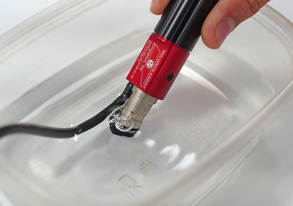
Wolverine Airsoft engines including the INFERNO, HYDRA, REAPER and BOLT all use either a 214 or 314 solenoid. In the event that dust or debris makes its way into the solenoid, it may become necessary to clean it.

Please see our Solenoid Maintenance Guide for detailed instructions on how to disassemble, maintain and reassemble your solenoid.

Solenoid
Maintenance Guide
www.wolverineairsoft.com
WOLVERINE AIRSOFT
Page 2
www.wolverineairsoft.com
Solenoid Maintenance
Wolverine Airsoft engines including the INFERNO,
HYDRA, REAPER and BOLT all use either a 214
or 314 solenoid. In the event that dust or debris
makes its way into the solenoid, it may become
necessary to clean it.
You will need:
• Compressed Air
• 2.5mm Allen Key
or 3mm square
bit for solenoids
with plastic caps
Begin by removing your solenoid
from your Wolverine Airsoft
engine by unscrewing it counter-clockwise from the engine.
The HYDRA will require the
additional step of removing the
retention clip from around the
valve housing.
MAC Valves 214, 2-Way Solenoid
MAC Valves 314, 3-Way Solenoid
Plastic Cap
(3mm
square bit)
Brass Cap
(2.5mm
allen key)
Page 3
www.wolverineairsoft.com
Use a 2.5mm Allen key or 3mm
square bit to remove the cap
from the solenoid by rotating
counterclockwise.
Use a blunt instrument to open
the valve by pushing on the piston in the center hole as shown
below. This will open the valve
for cleaning.
Replace the brass end cap
using the 2.5mm Allen key or
3mm square bit.
While holding the valve open
use compressed air to remove
the debris from the valve. It
is important to not scratch
the seal. The debris will usually
be found just behind the front
O-ring as indicated in the image.
Finally, reinstall the solenoid in
your engine and hand-tighten it.
www.wolverineairsoft.com
Need professional help?
To find a retailer close to you visit:
www.wolverineairsoft.com/dealers

Engine Maintenance

Regular maintenance on an HPA engine should be performed every 25-50k rounds depending on the conditions it is being used in. The dustier and dirtier the conditions, the more frequently it should be serviced. Maintaining the INFERNO requires disassembling the engine and lubricating/cleaning/replacing the O-Rings.

For detailed instructions, please see the Owner’s Manual for your engine.

For detailed instructions on the solenoid, please see the Solenoid Maintenance Guide.