AEG Conversion Kits include an HPA engine and airline as well as required electronics components for standard installations. For example, our INFERNO kits are available in the four options.
V2 Kit
INFERNO with M4 Nozzle
V2 Trigger Board
Premium FCU
14″ Wire Harness
V2 Spartan Kit
INFERNO with M4 Nozzle
Spartan Electronics
14″ Wire Harness
V3 Kit
INFERNO with AK Nozzle
V3 Trigger Board
Premium FCU
12″ Wire Harness
M249 Kit
INFERNO with M4 Nozzle
Premium FCU
M249 Wire Harness
Choosing the right kit
See the list below to ensure you obtain the correct kit for your replica. See also that some replicas require additional components not part of our standard kits. For example, for the A&K Masada, you’ll need to swap your INFERNO’s nozzle for an A&K Masada nozzle, as well as swap out your kit’s 14″ V2 Wire Harness for the shorter V3 12″ Wire Harness.
Note: This article pertains to the Legacy Bluetooth FCU and not the BLINC Bluetooth FCU!
To increase the dwell value for use with the REAPER, open the Legacy Bluetooth FCU app and navigate to the command line page. Enter D4444 in the command text line and press “Send command.”
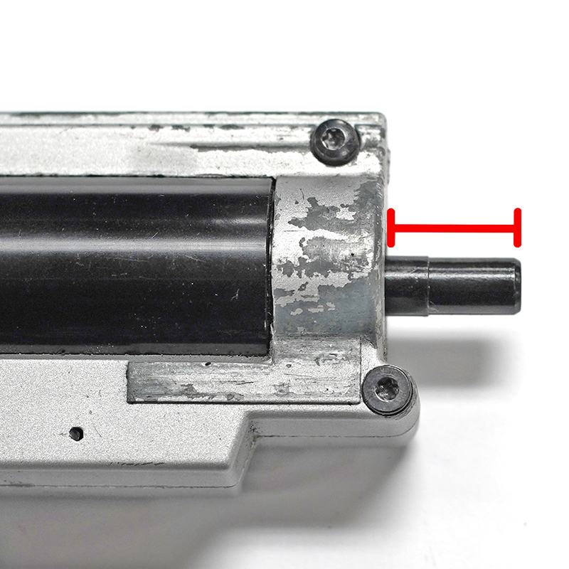
If you can’t find a nozzle specific to your replica, you can determine the correct nozzle by measuring the two distances indicated below and adding them together. Then choose a nozzle from the list that is 0 to 0.5mm longer than your measurement.
Original Engine
With your original engine and nozzle still in the gearbox, measure the distance the nozzle extends from the front of the gearbox.
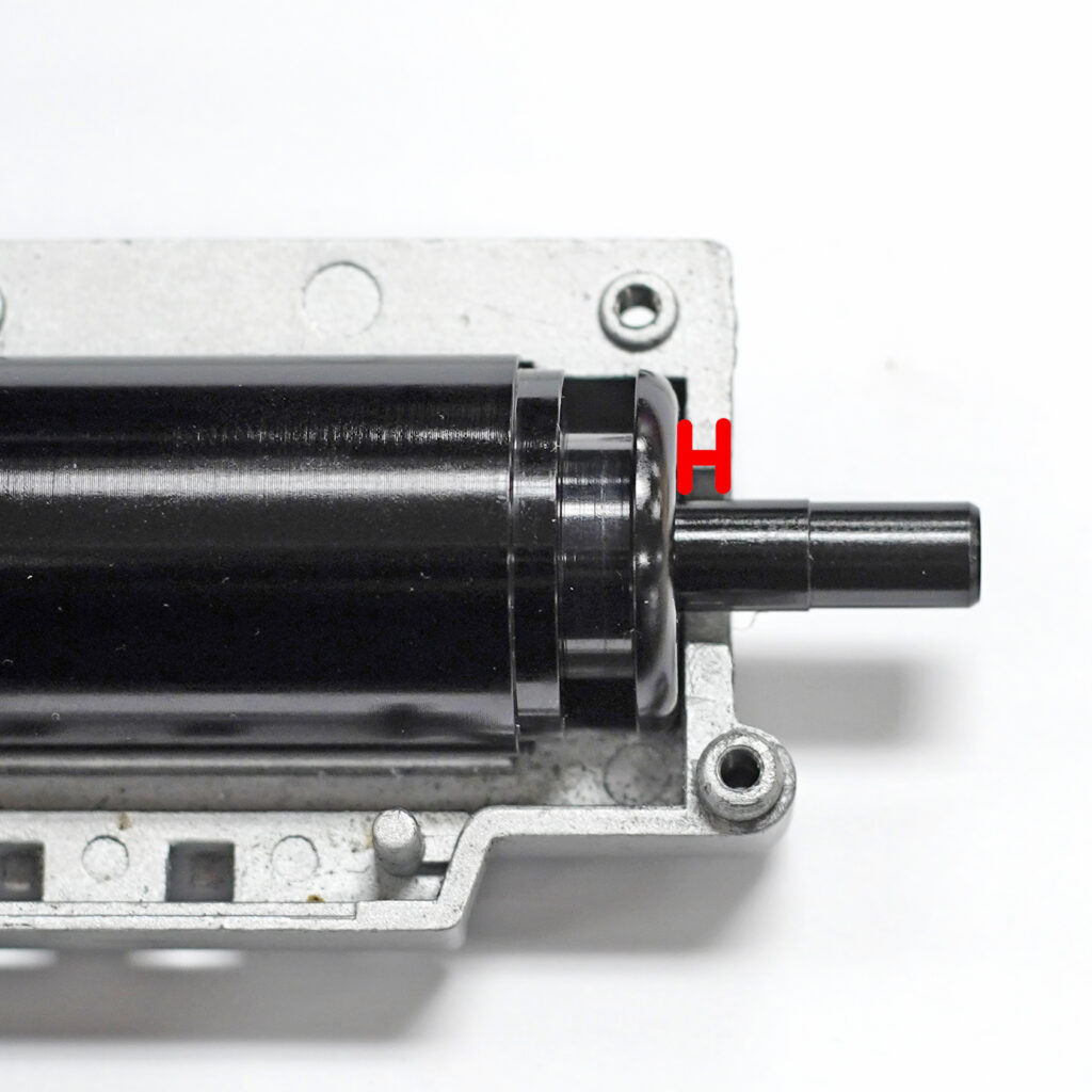
Wolverine Engine
With your Wolverine Airsoft engine in the gearbox, measure the distance from the front of the engine to the front of the gearbox and add it to your first measurement.
Nozzle
Length(mm)
CA LMG
17.75
M249
18.75
M4
19.25
AK
19.65
KA FAL
21.5
G36
24.5
CA SCAR L
25.75
PTS Masada
27.5
VFC XCR
29
A&K Masada
33.32
GG SR25
35.05
VFC SCAR H
36
KA SIG 556
47.4
Note: A&K SR25 and FAL nozzles are interchangeable. If you need a Gen 1 nozzle, select FAL. If you need a Gen 2 nozzle, select A&K SR25.