

Owner’s Manual for Legacy Bluetooth FCU
Discontinued products including the SMP, REAPER, QUAKE and Legacy versions of the STORM and WRAITH line.
Note: This article pertains to the Legacy Bluetooth FCU and not the BLINC Bluetooth FCU!
If you have forgotten your passkey or need to reset the passkey on your FCU, perform the following steps to reset the passkey.
For more information, see the Owner’s Manual
Note: This article pertains to the Legacy Bluetooth FCU and not the BLINC Bluetooth FCU!
To increase the dwell value for use with the REAPER, open the Legacy Bluetooth FCU app and navigate to the command line page. Enter D4444 in the command text line and press “Send command.”

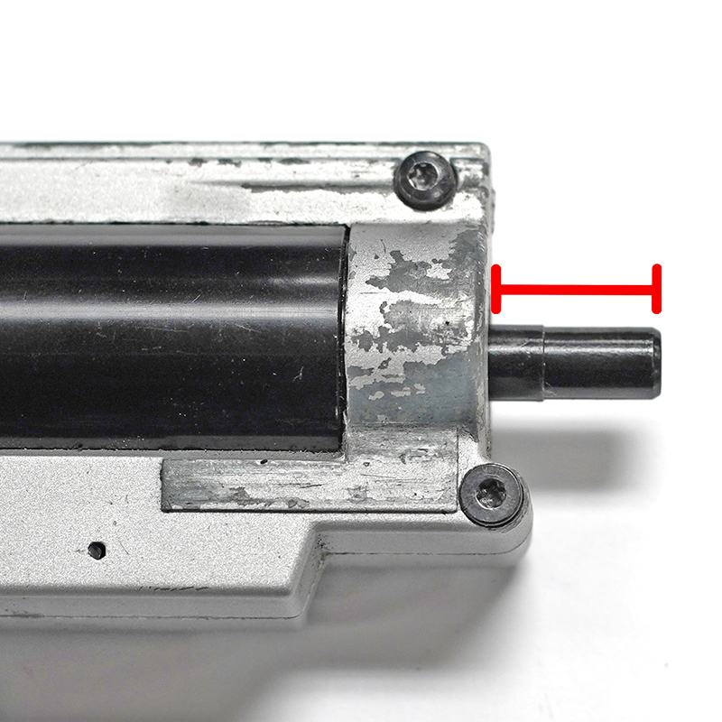
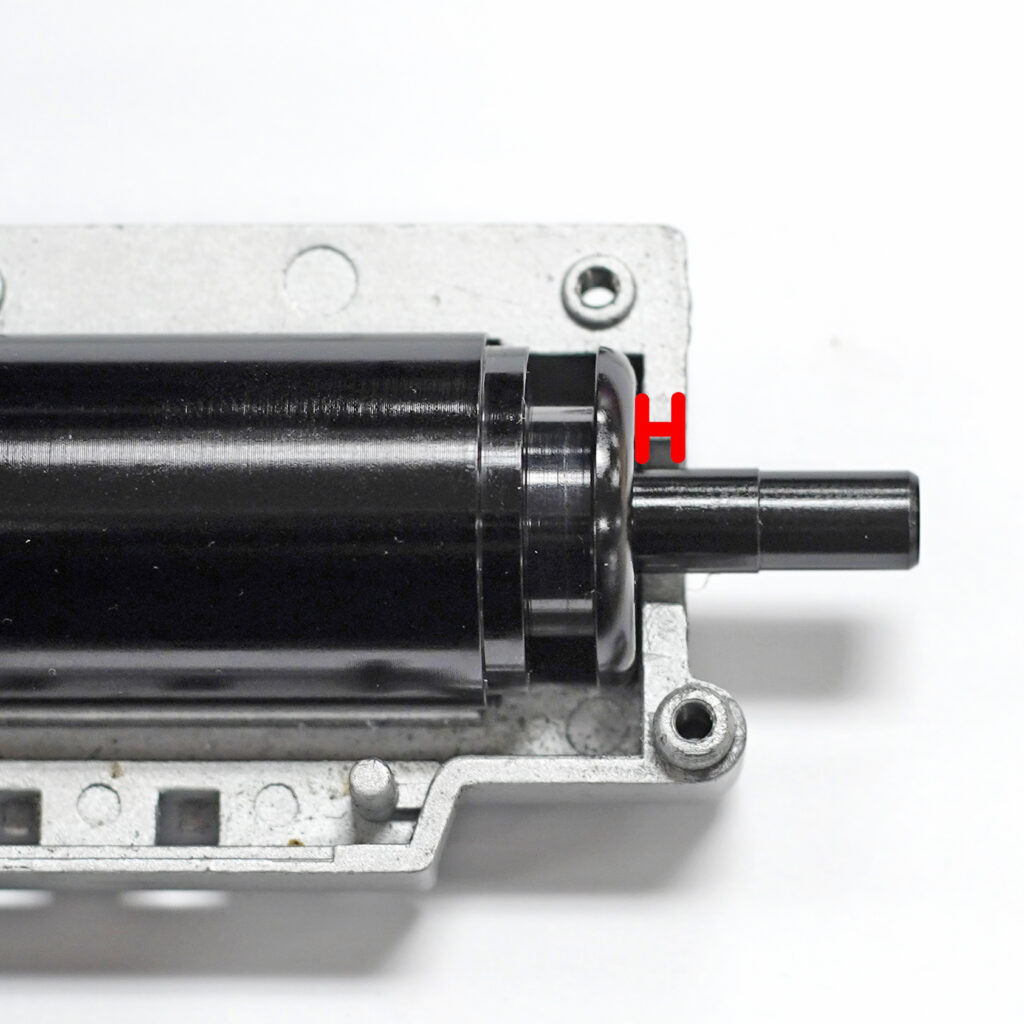
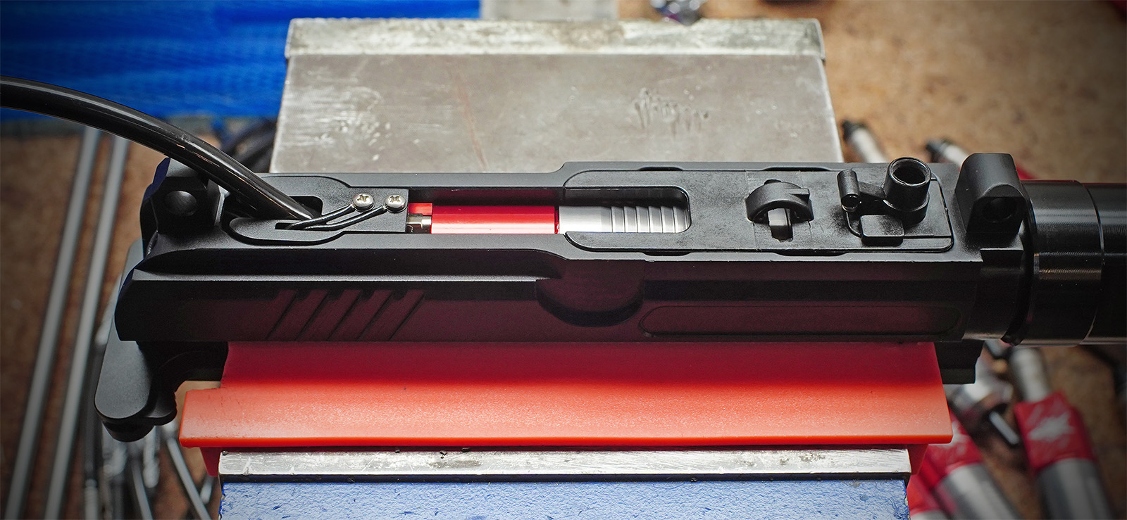
If you can’t find a nozzle specific to your replica, you can determine the correct nozzle by measuring the two distances indicated below and adding them together. Then choose a nozzle from the list that is 0 to 0.5mm longer than your measurement.
Original Engine
Wolverine Engine
| Nozzle | Length(mm) |
|---|---|
| CA LMG | 17.75 |
| M249 | 18.75 |
| M4 | 19.25 |
| AK | 19.65 |
| KA FAL | 21.5 |
| G36 | 24.5 |
| CA SCAR L | 25.75 |
| PTS Masada | 27.5 |
| VFC XCR | 29 |
| A&K Masada | 33.32 |
| GG SR25 | 35.05 |
| VFC SCAR H | 36 |
| KA SIG 556 | 47.4 |
Note: A&K SR25 and FAL nozzles are interchangeable. If you need a Gen 1 nozzle, select FAL. If you need a Gen 2 nozzle, select A&K SR25.
For detailed instruction on disassembling, lubricating or replacing O-Rings and reassembling your Legacy WRAITH CO2 Stock, please see the WRAITH CO2 Stock Maintenance Guide.
For the WRAITH X, please see the WRAITH X Owner’s Manual.

Rich demonstrates how to install the WRAITH mini airline onto the hardpoint adapter.
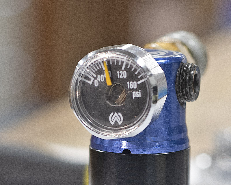
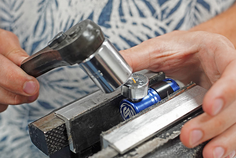
If your STORM Regulator gauge is stuck and/or the spring behind the needle (see photo) is visibly out of place, you will need to replace the gauge. You can get a replacement gauge here: https://www.wolverineairsoft.com/product/micro-gauge-for-storm-regulator/
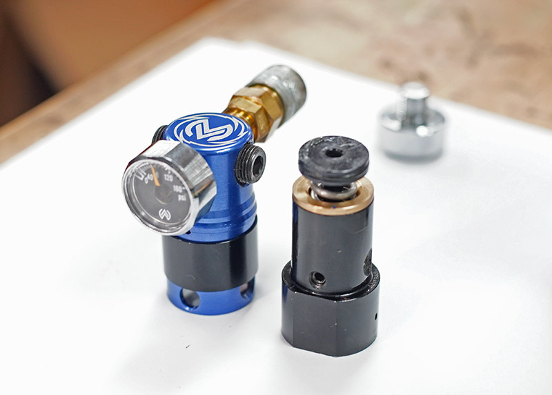
Disassemble the regulator cap from the base by removing the retention screws. Tighten the pressure adjustment screw so that the internals can be freely removed from the cap. Refer to the specific Owner’s Manual for your regulator for detailed information.
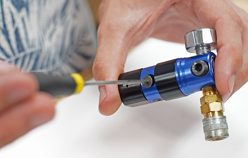
Ensure the internal parts of the regulator are completely removed from the regulator cap before continuing.
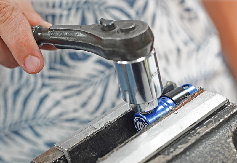
Remove the damaged gauge from the regulator cap with a 22mm hex socket, turning counter-clockwise. A vice is recommended.
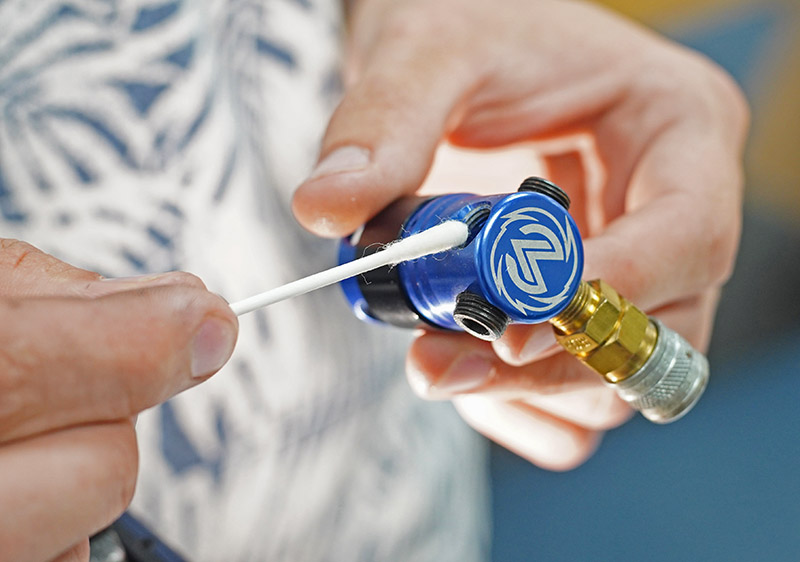
Clean the threads thoroughly inside the gauge port with acetone.
Wrap the threads of your new replacement gauge with PTFE (Teflon) thread tape.
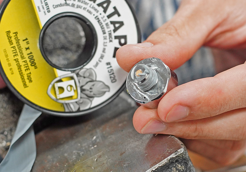
Thread the new gauge into the regulator cap using a 22mm hex socket. Turn the gauge clockwise 2 to 3 times and then orient the gauge as desired. Connect your regulator to an air source and ensure there are no leaks.
If your INFERNO Gen 2 is leaking, use this diagram to determine which O-ring may be faulty. For example, if your engine is leaking from around the nozzle, you should check the location and condition of O-ring #4.
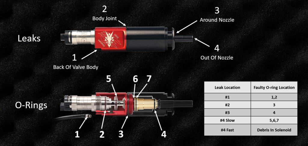
For instructions in replacing an O-ring, please see the INFERNO Gen 2 Owner’s Manual.
If your INFERNO Gen 2 is leaking, use this diagram to determine which O-ring may be faulty. For example, if your engine is leaking from around the nozzle, you should check the location and condition of O-ring #4.
For instructions in replacing an O-ring, please see the INFERNO Gen 2 Owner’s Manual.
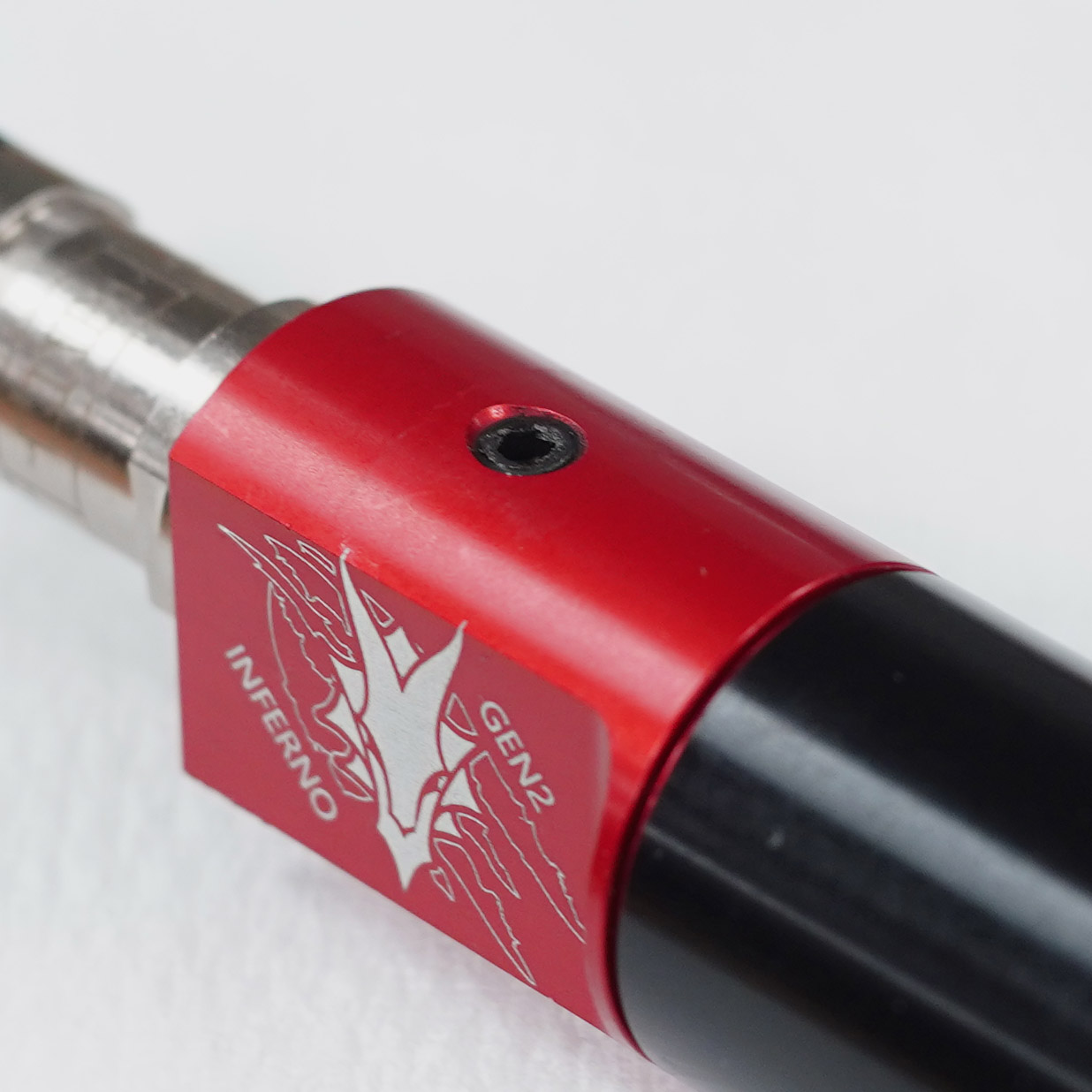
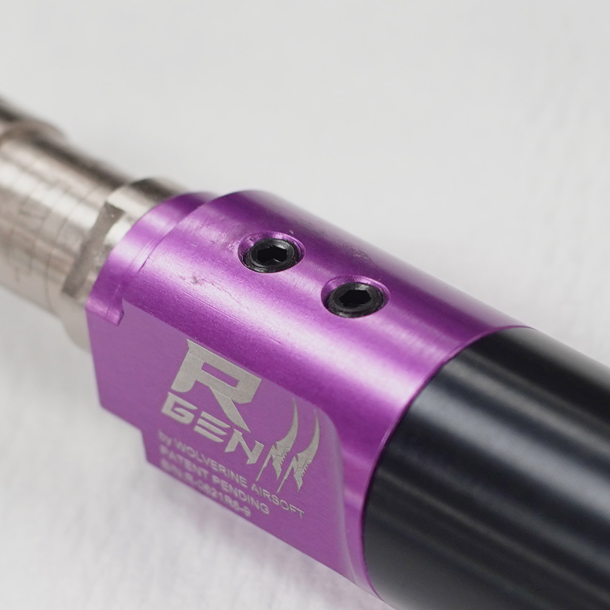
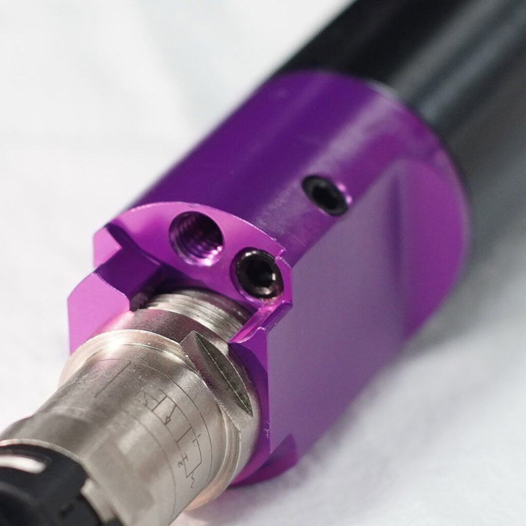
The cylinder plugs are part of the manufacturing process and are not adjustable or removable. Never attempt to remove or adjust the cylinder plugs. Doing so will cause leaking and engine malfunction. Already done it? Follow these steps…
See also: Solenoid Leaks